LOGIC GATES
*LOGIC GATES ;
Logic gates are the basic building blocks of any digital system. It is an electronic circuit having one or more than one input and only one output. The relationship between the input and the output is based on a certain logic. Based on this, logic gates are named as AND gate, OR gate, NOT gate etc.
*ANT GATE
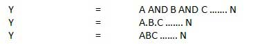
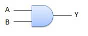
A circuit which performs an AND operation is shown in figure. It has n input (n >= 2) and one output.
Logic diagram
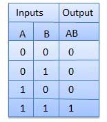
Truth Table
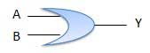
OR GATE
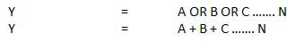
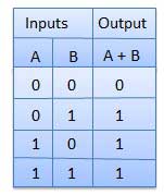
A circuit which performs an OR operation is shown in figure. It has n input (n >= 2) and one output.
Logic diagram
Truth Table
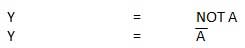
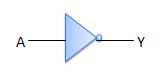
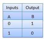
*NOT GATE
NOT gate is also known as Inverter. It has one input A and one output Y.
Logic diagram
Truth Table
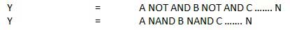
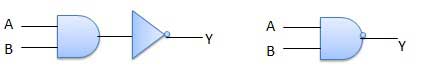
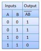
*NAND GATE
A NOT-AND operation is known as NAND operation. It has n input (n >= 2) and one output.
Logic diagram
Truth Table
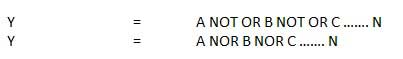
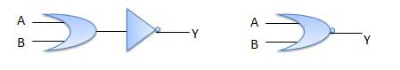
✓NOR GATE
A NOT-OR operation is known as NOR operation. It has n input (n >= 2) and one output.
Logic diagram
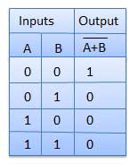
Truth Table
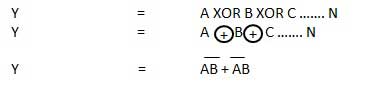
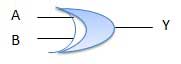
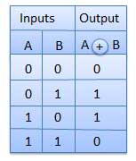
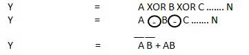
✓XORGate
XOR or Ex-OR gate is a special type of gate. It can be used in the half adder, full adder and subtractor. The exclusive-OR gate is abbreviated as EX-OR gate or sometime as X-OR gate. It has n input (n >= 2) and one output.
Logic diagram
Truth Table
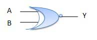
✓XNOR GATE
XNOR gate is a special type of gate. It can be used in the half adder, full adder and subtractor. The exclusive-NOR gate is abbreviated as EX-NOR gate or sometime as X-NOR gate. It has n input (n >= 2) and one output.
Logic diagram


Comments
Post a Comment